姜珏 祝义 王玮 印婵 张颖

摘要:针对面向数据流的软件设计方法缺乏有效的数据流图到软件结构图的转换工具问题,提出了面向数据流的软件设计方法并开发出了相应工具。首先,讨论了对用户绘制的数据流图进行存储的方法;其次,给出了数据流图到软件结构图转换的系列算法;最后,通过Java语言实现了数据流图到软件结构图转换的原型系统。实验表明该系统能够根据用户输入的数据流图生成满足用户需求的软件结构图,从而能够从根本上提高面向数据流的软件设计方法的效率。
关键词:数据流;軟件结构图;转换;原型系统;功能性测试
中图分类号:TP311? ? ? 文献标识码:A
文章编号:1009-3044(2020)32-0086-04
Abstract: Aim to data flow-oriented design lacks the transformation tool from dataflow diagram to software architecture diagram, this paper proposes data flow-oriented software design method and develops the corresponding tool. Firstly, a method is discussed to store data flow diagram which is input by the user. Secondly, a series of algorithms is given for the transformation from the data flow diagram to a software architecture diagram. Lastly, a prototype system is implemented for transforming the data flow diagram to a software architecture diagram. The experiments show that the software architecture diagram can be generated according to the dataflow diagram which is input by users, so it can improve the efficiency of data flow-oriented method.
Key words: data flow; software structure diagram; transformation; prototype system; functional test
1 背景
需求阶段和设计阶段是软件生命周期的两个重要阶段:需求阶段主要关注如何描述问题空间,而设计阶段则主要关注如何描述解空间[1-2]。自软件危机以来,软件的规模愈来愈大,需求到设计阶段的重要性也越来越高,设计的失误与变动往往需要很大的代价去维护[3]。在进行大型软件开发时,需求和设计阶段需要进行反复迭代与验证,直到设计能很好地支撑后续的软件开发[4-5]。
在面向数据流设计的方法中,数据流图(Data Flow Diagram, DFD)到软件结构图(Software Structure Diagram, SSD)的转换是举足轻重的环节,数据流图和软件结构图分别是需求阶段和设计阶段的制品,对后续的软件开发十分重要[6-7]。但是目前未知,简单易用的转换工具还没有开发出来,导致数据流图到软件结构图的转换迄今为止还是建立在设计人员的设计经验上,以人为的方式进行着[8-9]。
数据流图分为事务型和变换型,事务型的转换比较简单,并且在实际中变换型的数据流图使用更为广泛,所以本文将主要针对变换型的数据流图到软件结构图的转换展开研究,并给出行之有效的分析与设计方法,在此基础上开发一个原型系统,以期为设计和开发高质量的现代大型复杂软件系统提供坚实的理论基础和相应的工具支持。
本文将研究数据流图到结构图的转换,从而实现面向数据流的软件设计方法,并在此基础上设计相应的转换工具。
2 系统的设计与实现
基于模型转换的数据流图到软件结构图的转换系统的开发过程分为以下几个阶段。
2.1 需求分析
2.1.1 数据流图的绘制存储
数据流图是一种图形化技术,是系统逻辑功能的图形表示,它描绘信息流和数据从输入移动到输出的过程中所经受的变换。包含4种基本符号,正方形(或立方体)表示数据的源点和终点,圆形(或圆角矩形)代表变换数据的处理,两条平行横线(或开口矩形)代表数据存储,箭头表示数据流,即特定数据的流动方向[10-11]。
为了完成数据流图的绘制,系统需要包含绘制模块,提供绘制面板以及绘制以上4种基本符号的方法,同时实现对图形的细化处理,实现以下功能:
1)对选定图形进行拖动;
2)对选定图形进行大小调整;
3)对选定图形进行添加文字。
此外,为了降低系统的耦合度,并且保证绘制的数据流图能够持久使用,还需实现将绘制的数据流图,以一定的形式保存到本地的功能。
2.1.2 数据流图转换为软件结构图
设计转换算法,读取本地保存的数据流图,并进行解析,实现与代码进行对接,完成数据流图到软件结构图的转换,保存转换后的数据到本地。
2.1.3 显示软件结构图
实现显示和修改软件结构图功能。反编译转换后的数据,通过绘制模块,将转换算法输出的数据进行映射显示,得到软件结构图,同时,用户可对得到的软件结构图进行修改调整,得到合适的软件结构图,最后还需实现将软件结构图以一定的形式保存到本地的功能。
2.2 原型系统设计
2.2.1 输入模块
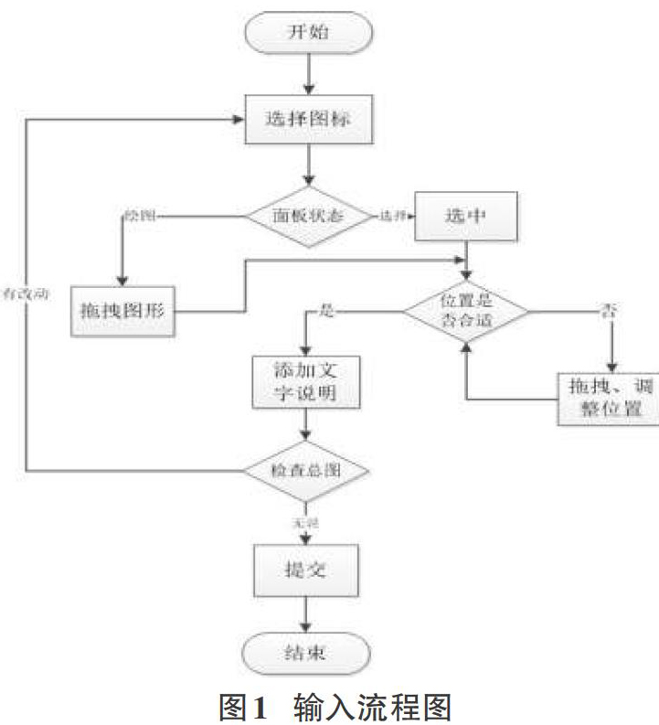
输入模块采用主流的绘画界面设计,用户可以用拖曳图形的方式自由绘制数据流图,绘图界面会为用户提供基本绘制图形。框架实现了拖曳、缩放、旋转、自定义属性等基础操作,开发者只用关心图表绘画实现即可。
由于系统无法对处理元素进行细分,因此在绘图界面需要用户自主选择处理元素是输入子元素,处理子元素还是输出子元素。在用户绘制数据流图时,每新建的一个结点或边,都会随机生成ID,用于区分每个元素,便于后台转换处理。
输入模块将用户绘制的数据流图以json的格式保存至本地,转换模块只需读取解析本地的json文件进行处理,前后台的工作任务相对较为独立。
输入模块的绘制流程图如图1所示。
2.2.2 转换模块
转换模块采用JAVA语言,根据数据流图的json对象编写一个实体类用于接收整个数据流图,此类中包含所有结点和边的信息、随机生成的ID号。扫描类对象的所有节点后,构造出对应十字链表的所有包含源结点信息的新结点,同时根据类对象中所有边结点的弧头弧尾信息构造十字链表。将存储着整张数据流图的十字链表转换成树后,以树的形式存储软件结构图并将其投影至用户界面。
2.2.3 输出模块
输出模块的过程是输入模块的逆序执行过程,将软件结构图对应的树转换的对象反编译后以json文件的形式保存本地。在此过程中,根据类对象中每个结点的信息计算出它们的投影坐标,后续任务按照顺序执行即可。用户可以在前台读取文件,进一步显示软件结构图。
2.2.4 编码实现
1)转换模块核心代码:
构造十字链表
public static OLGraph getOLGraph(DFD dfd){
OLGraph graph = new OLGraph();
graph.setNodeNum(dfd.getNodes().size());
graph.setArcNum(dfd.getLines().size());
Map
for (int i = 0; i < dfd.getNodes().size() ; i++) {
NodesEntity nodeEntity = dfd.getNodes().get(i);
Node node = new Node(nodeEntity.getId(),nodeEntity.getText(),ClassifyType.getType(nodeEntity),null,null);
graph.getNodes().add(node);
map.put(node.getId(),node);
if(node.getType().equals("origin"))
graph.getOrigins().add(node);
}
for (int i = 0; i < dfd.getLines().size(); i++) {
LinesEntity lineEntity = dfd.getLines().get(i);
Node tail = map.get(lineEntity.getFrom().getId());
Node head = map.get(lineEntity.getTo().getId());
Arc arc = new Arc(tail,head,null,null,lineEntity.getText());
构造出度 将这条边放在相同弧尾的边节点后
Arc tailArc = tail.getFirstout();
Arc tailLink = null;
if(tailArc==null) {
tail.setFirstout(arc);
}
else{
tailLink = tailArc.getTlink();
while (tailLink!=null){
tailArc=tailLink;
tailLink=tailLink.getTlink();
}
tailArc.setTlink(arc);
}
構造入度 将这条边放在相同弧尾的边节点后
Arc headArc = head.getFirstin();
Arc headLink = null;
if(headArc==null) {
head.setFirstin(arc);
}
else{
headLink = headArc.getHlink();
while (headLink!=null){
headArc=headLink;
headLink=headLink.getHlink();
}
headArc.setHlink(arc);
}
}
return graph;
}
十字链表转换成树
public static ChildTree getTree(OLGraph olGraph) {
第一遍遍历构造input模块
for (Node origin : olGraph.getOrigins()) {
拿到input头节点
CTNode pre = tree.getNodes().get(1);
DFSTraverse1(pre, origin);
}
第二遍遍历构造process模块和output模块
set = new HashSet<>();
for (Node node : input) {
pre1是process头节点 pre2是output头节点
CTNode pre1 = tree.getNodes().get(2);
CTNode pre2 = tree.getNodes().get(3);
DFSTraverse2(pre1, pre2, node);
}
逆置树的input模块的结点
ReverInput(tree);
return tree;
}
2)输出模块核心代码
input模块的所有节点构造
Queue
queue.add(input);
int inputLayer = -1 ;? ? 当前遍历到input的层数
int inputIndex = 0 ;? ? 当前遍历到该层的第几个
while (!queue.isEmpty()){
int size = queue.size();
inputLayer++;
inputIndex = 0;
int layer = inputLayerCount.get(inputLayer);? 当前层数的节点个数
int start = 0;
if(layer!=inputMaxLayer)
start = (inputX - inputWidth/2) +( (inputMaxLayer - layer) * 150 + (? (inputMaxLayer - layer) * 50 ) )/ 2 + 75;
else
start = inputX - inputWidth/2 + 75;
for(int i = 0 ; i < size ;i++){
CTNode node = queue.poll();
if(node.getId().equals(input.getId())){
NodesEntity inputEntity = getNodeEntity(inputX, inputY, tree.getNodes().get(1));
dfd.getNodes().add(inputEntity);
map.put(inputEntity.getId(),inputEntity);
CTArc child = node.getFirstChild();
while(child != null){
queue.add(child.getTo());
child = child.getLink();
}
}
else {
inputIndex++;
int? x = start + (inputIndex - 1) * 150 + (inputIndex - 1) * 50;
int y = inputLayer * 150 + inputY ;
NodesEntity nodeEntity = getNodeEntity(x, y, node);
dfd.getNodes().add(nodeEntity);
map.put(nodeEntity.getId(),nodeEntity);
CTArc child = node.getFirstChild();
while(child != null){
queue.add(child.getTo());
child = child.getLink();
}
}
}
}
構造边节点
Set
for (CTArc ctArc : arcSet) {
dfd.getLines().add(getLineEntity(ctArc));
}
2.3 系统测试结果
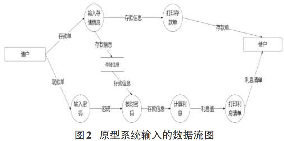
图2是一个银行存取款系统的数据流图。
经过原型系统的转换后,图3软件结构图如下所示。
3 结束语
本文主要研究了数据流图到软件结构图的转化,并开发一个原型系统。首先我们了解了数据流图到软件结构图的转换方法研究现状和相关背景。然后,我们对此项目进行了需求分析。接下来,我们在系统的设计与实现过程中主要分析了输入、转换、输出三大模块的内容,并且展示了相关核心代码。最后,我们对已完成的原型系统进行功能性测试。测试结果正确,我们展示了测试所用的数据流图和得出的软件结构图。此测试结果证明了本文实现了从数据流图到软件结构图的转化。
参考文献:
[1] 祝义.嵌入式软件需求规约到软件体系结构模型的转换研究[D].南京:南京航空航天大学,2011.
[2] 梅宏,申峻嵘.软件体系结构研究进展[J].软件学报,2006,17(6):1257-1275.
[3] Svetinovic D.Architecture-level requirements specification[J].Second International Workshop from Software Requirements to Architectures (STRAW'03),2003:14-19.
[4] Hong M.A complementary approach to requirements engineering—software architecture orientation[J].ACM SIGSOFT Software Engineering Notes,2000,25(2):40-45.
[5] Hofmeister C,Nord R,Soni D.Applied Software Architecture[M].Boston: Addison-Wesley Professional, 2010.
[6] Zhang W,Mei H,Zhao H Y,et al.Transformation from CIM to PIM:A feature-oriented component-based approach[M]//Model Driven Engineering Languages and Systems.Berlin,Heidelberg:Springer Berlin Heidelberg,2005:248-263.
[7] Medvidovic N,Dashofy E M,Taylor R N.The role of middleware in architecture-based software development[J].International Journal of Software Engineering and Knowledge Engineering,2003,13(4):367-393.
[8] Rajasree M S,Reddy P K,Janakiram D.Pattern oriented software development: Moving seamlessly from requirements to architecture[C]//Proc. of the 2nd International Software Requirements to Architectures Workshop, 2013:54-60.
[9] Brandozzi M,Perry D E.From goal-oriented requirements to architectural prescriptions: The preskriptor process[C]//Proc. of the 2nd International Software Requirements to Architectures Workshop, 2013: 107-113.
[10] Shao W Z. Object Oriented System Analysis[M]. Beijing: Tsinghua University Press, 2008.
[11] Buhr R J A.Use case maps as architectural entities for complex systems[J].IEEE Transactions on Software Engineering,1998,24(12):1131-1155.
【通聯编辑:谢媛媛】
- 浅析优化农业综合执法的策略
- 林业种苗管理中的常见问题及应对措施探讨
- 不同分离培养条件对松乳菇菌丝的影响研究
- 松材线虫病伐除迹地木本植物的自然恢复分析
- 杨潜叶叶蜂风险评估及防治对策
- 以棉花种植为例探讨新疆低碳农业发展
- 2019年田丰玉米品种联合体生产试验研究
- 落叶松冠幅大小对林下光照强度的影响研究
- 不同品种草莓的引进栽培与果实感官评价研究
- 发掘珍稀资源 传承优良种质
- 农产品电商发展格局正在重塑
- 蒲县:让“县长代言”成为县域经济有效增长点
- 加快完善种质资源保护体系 扎实开展种质资源登记
- 农机管理中存在的问题与应对策略
- 浅析农业机械化对现代农业的促进作用
- 农业经济管理在新农村建设中的优化策略研究
- 浅谈林权登记发证工作中存在的问题及对策
- 提高北方森林培育质量的若干途径
- 农垦农业技术推广服务体系的建设与运转初探
- 林业技术创新在现代林业发展中的重要性
- 农产品质量安全检测现状及提升方法探讨
- 金叶榆的养护管理及病虫害防治
- 无公害防治技术在林业病虫害防治中的应用
- 浅析绿色农业种植技术的推广要点
- 华山松的病虫害防治策略探析
- staunch¹
- stave
- staved
- staves
- stave sth off
- stave sth ↔ off
- staving
- stay
- stay afloat
- stay after school
- stay alive
- stay-at-home
- stayathome
- stay away
- stay away from/keep away from
- stay away from sb/sth
- stay away/keep away
- stay back
- stay behind
- stay close/keep close
- stay cool/keep cool
- stayed
- stayed in
- stayed on
- stayed out
- 阿瞒
- 阿瞒请客——珍馐
- 阿磨
- 阿私
- 阿私所好
- 阿章
- 阿童
- 阿米巴
- 阿米巴病
- 阿紫
- 阿紫迷人
- 阿緆
- 阿纵
- 阿练
- 阿细跳月
- 阿绎
- 阿结
- 阿绵花屎
- 阿罔
- 阿翁
- 阿老
- 阿育王
- 阿育王寺
- 阿胡
- 阿胶