袁善坤 储江伟 李洪亮 张民安


摘 要:为探究电动汽车在ABS作用下的电机制动特性,本文基于汽车单轮模型,建立电动汽车动力学模型,构建液压制动系统传递函数,设计基于PID控制原理的ABS模型。选用永磁同步电机,采用id = 0控制策略,利用坐标变换原理,对永磁同步电机进行矢量控制,并起制动作用。设计制动力传输系统,实现制动力矩的传递。设定单轮电动汽车模型参数及制动初速度为25 m/s,利用simulink建立电动汽车单轮制动模型并进行仿真实验。研究分析制动过程中,在ABS作用下,单轮电动汽车模型的滑移率的变化情况;在有无电机制动情况下,液压制动力矩的变化对比;电机制动时,定子三相输出电流的变化情况。仿真结果表明:制动时,电机转子切割磁感线,产生感应电流,则电机回收部分制动能量,该模型能够得出可观的仿真结果。
关键词:单轮模型;仿真试验;ABS;矢量控制;电机制动
中图分类号:U461.1文献标识码:A文章编号:1006-8023(2018)06-0038-05
Simulation of Motor Braking under the ABS based on Simulink
YUAN Shankun, CHU Jiangwei*, LI Hongliang, ZHANG Minan
(School of Traffic, Northeast Forestry University, Harbin 150040)
Abstract: In order to investigate the characteristics of electric motor braking under the action of ABS, a dynamic model of electric vehicle based on the single wheel model of the vehicle is built, the transfer function of the hydraulic brake system is constructed, and an ABS model based on the PID control principle is designed. The permanent magnet synchronous motor is selected and the id=0 control strategy is adopted. The principle of coordinate transformation is used to perform vector control of the permanent magnet synchronous motor and the motor act as a brake. Braking force transmission system is designed to achieve the transmission of braking torque. The parameters of single-wheel electric model are set and initial braking speed is set at 25m/s. The single-wheel braking model for electric vehicles is established using simulink and simulation experiments are conducted. We study and analyze the changes of the slip rate of the single-wheel electric vehicle model under the action of ABS during the braking process, the changes of the hydraulic brake torque under the condition of whether the motor braked and the stator three Phase output current changes, when the motor brakes. The simulation results show that when the motor rotor cuts the magnetic line, the induction current is generated, then the motor can recover part of the braking energy, and the model can get a considerable simulation result.
Keywords: Single wheel model; simulation; ABS; vector control; motor brake
0 引言
再生制動能量回收可回收电动汽车减速制动时的部分动能,并将其转化为电能储存起来, 是解决电动汽车因电池密度低导致的续驶里程短的一种有效措施[1-2]。ABS能够防止前后车轮制动时被完全抱死,从而提高了汽车在制动过程中的稳定性和操纵性, 缩短制动距离, 防止轮胎过度磨损[3-4]。
制动能量回收兼顾制动安全性为目标, 提出了再生制动与ABS的集成控制策略[5-6]。制动过程中车辆的复合制动与ABS兼容的问题是制动能量回收系统成熟化过程中必须着重解决的技术问题。
1 电动汽车液压制动模型建立
1.1 单轮制动模型
为建立电动汽车单轮车辆模型,对电动汽车进行假设[7]:
(1)汽车的质量均匀地分布在每个车轮上。
(2)汽车被认为是在平坦的地面上行驶。
(3)不考虑由于汽车绕直线旋转或者是其它车轮上不均匀制动而造成的运动规律。
(4)在直线行驶制动时,不存在轮胎的侧向力问题。
(5)被控系统认为是无传输延迟的动态线性系统。
(6)不考虑直线车辆动力学和单轮旋转动力学中的风阻作用。
(7)省略与支撑有关的全部垂直动力学假设。
如图1所示,对模型中车体在行驶方向和车轮绕主轴方向两个自由度建立动力学方程,可得简化的车辆动力学方程为[8]:
M·a = - F。? ? ? ? ? ? ? ? ? ? ? ? ? ? ? (1)
I·ωg? ?= Fxb·r-Tμ-Tg。? ? ? ? ? ? ? ? ? (2)
Fxb = μ·Fz。? ? ? ? ? ? ? ? ? ? ? ? ? ? ? ? ? ?(3)
式中:M 为单轮车辆模型质量,kg;a为汽车加速度,m/s2;F为轮胎受的地面附着力,N;I为车轮转动惯量,kg·m2;ω为车轮角速度,r/min;Fxb为地面制动力,N;r为车轮滚动半径,m;Tμ为车轮制动器摩擦力矩,N;Tg为电动机制动力矩,N;va为汽车行驶速度,m/s;W为单轮轮垂直载荷,即车体四分之一载荷,N;FP为车轴对车轮的推力,N;Fz为地面对车轮的法向反作用力,N;
μ为地面摩擦系数。
根据车轮纵向附着系数μ和滑移率S的关系,见表1。
采用双线性模型来简化轮胎模型,根据表1,推导出轮胎的双线性模型表达式为:
μ = 4.9S? ? ? ? ? ? ? ? ? ? ? ? ? ? ? ? ? ? ? ? ? ? ? ? ? ?(4)
μ = -0.3714S + 1.05428。
1.2 液压制动系统模型
在液壓制动系统中,假设制动器为理想元件,且制动器制动力矩Tμ与制动系压力呈线性关系,并无滞后影响。 液压传动过程中,忽略电磁阀弹簧的非线性因素、时间常数及压力传送的延迟。将其简化为一个电磁阀环节、一个弹性阻尼环节和一个积分环节,以控制器的控制信号为输入,以制动器的制动力矩Tμ为输出,制动系统传递函数为:
电磁阀的时间常数Tk远远小于弹簧阻尼系统的时间常数T,将Tk取0,Ts取0.01,同时Kp取21,K取100。
1.3 PID控制器设计
所采用的PID控制器是以期望滑移率S0与实际滑移率S偏差作为为输入:
e = ?S = S0 - S 。? ? ? ? ? ? ? ? ? ? ? ?(6)
采用仿真实验加试凑的方法,根据ABS的动态特性,得到干燥混凝土路面条件下的PID控制参数,Kp? = 45,Ti = 12.44,Td = 2.4。将S = 0.2设定为最佳滑移率。
2 电动汽车电机制动模型
2.1 永磁同步发电机模型
由于永磁同步电机的高效率、轻量化、高性能、高动态性能等特点,使永磁同步电机应用于电动汽车领域[9-10]。为了简化分析,忽略电机饱和与转子磁场谐波,永磁同步发电机在同步坐标(d-p坐标)下的数学模型为[11]:
式中:id、 iq、ud 和uq分别是定子d轴和q轴的电流和电压;Rs为定子电阻;ωe为发电机的电角频率;Ld和Lq分别为定子d轴和q轴的电感;λ0是永磁磁链。
永磁同步发电机的电磁转矩表示为[12-13]:
式中:P为永磁同步发电机的极对数。
2.2 坐标变换
d-p坐标系与α-β坐标系的变换,即park变换[14-15],其传递矩阵为:
式中:θ为d轴与α轴的夹角。
A-B-C坐标系与α-β坐标系的变换[16-17],即clark变换,其传递矩阵为:
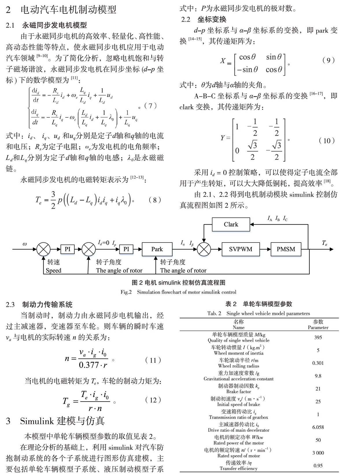
采用id = 0控制策略,可以使得定子电流全部用于产生转矩,可以大大降低铜耗,提高效率[18]。
由2.1、2.2得到电机制动模块simulink控制仿真流程图如图2所示。
2.3 制动力传输系统
当制动时,制动力由永磁同步电机输出,经过主减速器,变速器至车轮。则车辆的瞬时车速va与电机的实际转速n的关系为:
当电机的电磁转矩为Te,车轮的制动力矩为:
3 Simulink建模与仿真
本模型中单轮车辆模型参数的取值见表2。
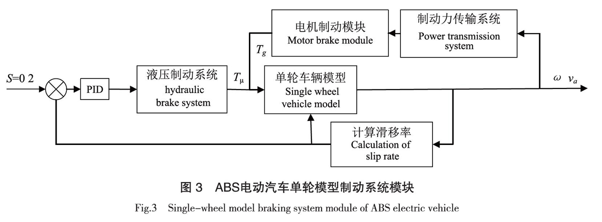
在理论分析的基础上,利用simulink对汽车防抱制动系统的各个子系统进行图形仿真建模,主要包括单轮车辆模型子系统、液压制动模型子系统、电机制动模型子系统。基于PID控制的ABS电动汽车单轮模型制动系统模块的关系如图3所示。
在干燥混凝土路面下,制动初速度为25 m/s,不带电机制动模块时,制动时间为2.65 s,制动距离为33.83 m;带有电机制动模块时,制动时间为2.65 s,制动距离为33.58 m。电动制动0.5 s后,ABS控制滑移率始终S = 0.2,滑移率的仿真结构如图4所示。
液压制动力矩的仿真结果如图5所示。当电动汽车开始制动时,由于液压制动力矩小,电机制动力矩主要发挥制动作用。液压制动力矩迅速增加,0.4 s后达到稳定值。带有电机制动时,液压制动力矩约为930 N·m;不带有电机制动时,液压制动力矩约为1 290 N·m。
当制动时,电机处于发电模式,车轮带动电机转子切割磁感线产生感应电流,将部分制动能量转化为电能。当运行到0.55 s时,电机的励磁电流输出幅值到达最大约10 A。电流经过平稳变化,稳态时,接近正弦波。在该矢量控制系统下,永磁同步电机具有良好的控制性能,动态性响应快,稳态性能良好,如图6所示。
4 结论
(1)仿真结果表明,该电动汽车单轮制动系统模型具有较强的鲁棒性。
(2)在整个电动汽车制动过程中,基于PID控制的ABS控制器能够与电机制动系统进行联合制动,并且发挥了防抱死作用,使滑移率维持在0.2左右。
(3)当有电机制动时,所需液压制动力矩与无电机制动时相比较小,并且电机发电模式的输出电流较平稳,能够回收电动汽车的部分动能。
【参 考 文 献】
[1]KIM S H, KWON O J, HYON D, et al. Regenerative braking for fuel cell hybrid system with additional generator[J]. International Journal of Hydrogen Energy, 2013, 38 (20):8415-8421.
[2]ZHANG J, LI Y, LV C, et al. New regenerative braking control strategy for rear-driven electrified minivans[J]. Energy Conversion and Management, 2014, 82:135-145.
[3]李振兴,周晶晶.基于SIMULINK的车辆防抱死制动系统控制研究[J].价值工程, 2016,35(7):102-104.
LI Z X, ZHOU J J. Study on control of vehicle anti-lock braking system based on simulink[J]. Value Engineering, 2016, 35(7):102-104.
[4]李志高. 汽車ABS的控制算法与仿真研究[D].武汉:武汉理工大学, 2011.
LI Z G. Control algorithm and simulation research of automotive ABS[D]. Wuhan: Wuhan University of Technology, 2011.
[5]靳立强,孙志祥,王熠,等.基于模糊控制的电动轮汽车再生制动能量回收研究[J].汽车工程, 2017,39(10):1101-1105.JIN L Q, SUN Z X, WANG M, et al. Research on regenerative braking energy recovery of electric wheel vehicle based on fuzzy control[J]. Automotive Engineering,2017,39(10):1101-1105.
[6]LI H. Research on integrated control strategy of regenerative braking system and ABS for pure electric vehicle[D]. Wuhan: Wuhan University of Technology, 2012.
[7] 李柏华. 汽车防抱死系统(ABS)建模与模糊PID控制研究[D].广州:华南理工大学, 2012.
LI B H. Research on anti-lock braking system (ABS) modeling and fuzzy PID control[D]. Guagnzhou: South China University of Technology, 2012.
[8]谷昭斌,陈丁跃,景琳浪.基于Simulink的汽车ABS仿真研究[J].汽车实用技术, 2012(7):27-30.
GU Z H, CHEN D Y, JING L L. Simulation research of automobile ABS based on simulink[J]. Automotive Practical Technology, 2012(7): 27-30.
[9]ALIZADEH M, KOJORI S S. Augmenting effectiveness of control loops of a PMSG (permanent magnet synchronous generator) based wind energy conversion system by a virtually adaptive PI (proportional integral) controller[J]. Energy, 2015(91): 610-629.
[10]张越雷,高剑,黄守道,等.SVPWM调制策略下永磁同步发电机损耗分析[J].湖南大学学报(自然科学版), 2016,43(10):87-93.
ZHANG Y L, GAO J, HUANG S D, et al. Losses analysis of permanent magnet synchronous generator under SVPWM modulation strategy[J]. Journal of Hunan University (Nature Science), 2016, 43(10): 87- 93.
[11]萬中奇. 永磁同步发电机预测直接转矩控制策略研究[D].杭州:浙江大学, 2013.
WAN Z Q. Research on predicting direct torque control strategy of permanent magnet synchronous generator[D]. Hangzhou: Zhejiang University, 2013.
[12]肖春燕. 电压空间矢量脉宽调制技术的研究及其实现[D].南昌:南昌大学, 2005.
XIAO C Y. Research and implementation of voltage space vector pulse width modulation technology[D]. Nanchang: Nanchang University, 2005.
[13]周恒. 基于空间矢量PWM控制的永磁同步电机驱动系统的研究[D].广州:华南理工大学, 2012.
ZHOU H. Research on permanent magnet synchronous motor drive system based on space vector PWM control[D]. Gangzhou: South China University of Technology, 2012.
[14]黄秋芳.电动汽车用交流电机矢量控制系统MATLAB仿真分析[J].海峡科学, 2010(12):88-90.
HUANG Q F. Simulation and analysis of AC motor vector control system for electric vehicle[J]. Straits Science, 2010(12): 88-90.
[15]宋晓琳,胡顺斌,张梦洁.农用电动车用永磁同步电机矢量控制系统研究[J].江苏农业科学, 2018,46(2):181-184.
SONG X L, HU S B, ZHANG M J. Research on vector control system of permanent magnet synchronous motor used in agricultural electric vehicles[J]. Jiangsu Agricultural Sciences, 2018, 46(2): 181-184.
[16]何耀,杨旭光,刘新天,等.电动汽车再生电能制动控制策略研究[J].计算机仿真, 2018,35(2):95-100.
HE Y, YANG X G, LIU X T, et al. Research on renewable energy brake control strategy for electric vehicles[J]. Computer Simulation, 2018, 35(2): 95-100.
[17]顾勇.适合电动ATV使用的电驱动系统分析[J].林业机械与木工设备,2018,46(10):41-43.
GU Y. Analysis of electric drive system suitable for electric ATVs[J].
Forestry Machinery & Woodworking Equipment,2018,46(10):41-43.
[18]龙明贵. 永磁同步电机矢量控制分析[D].昆明:西南交通大学, 2012.
LONG M G. Permanent magnet synchronous motor vector control analysis[D]. Kunming: Southwest Jiaotong University, 2012.
- 语文复习课应科学选择课型
- 践行“适合教育”理念 发展教师教学智慧
- 壮汉双语教学促进学生学习汉语文的有效策略探究
- 浅谈多媒体在农村语文教学中的有效运用
- 语文教学中渗透儿童哲学教育初探
- 构筑生命的厚度与深度
- 培养思维品质,发展学生的英语核心素养
- 聚焦核心素养 利用情境活动 开发校本课程
- 英语绘本教学的实践与思考
- 创客背景下信息技术教学创新探索
- 科学教学中学生探究思维的培养策略
- 浅谈儿童化科学记录单的设计与改进
- 让经典文化为《道德与法治》课堂增色添彩
- 在儿童文化营造中培养道德与法治观念
- 道德与法治教学中多媒体的运用实践
- 体验式学法在道德与法治教学中应用切点分析
- 谈学生作业的自主批改
- 从“野”出发,“趣”无止境
- 浅谈农村幼儿教育均衡发展的内核构建
- 班主任角色定位的深层追问
- 播种关爱,迟开花朵亦争春
- 对优化小学德育工作的思考与实践
- 生命成长
- “远程协同课堂”教学的实践与思考
- 儿童幸福成长课程的开发建构及其成果概述
- preciser
- precises
- precisest
- precising
- precision
- precisional
- precisionengineering
- precisionists
- precisions
- precision's
- precisses
- precitation
- precitations
- precivilization
- pre-civilization
- precivilizations
- preclad
- pre-claim
- preclaim
- preclaimant
- preclaimants
- preclaimed
- preclaiming
- preclaims
- preclassically
- 修饰2
- 修饰3
- 修饰仪表
- 修饰使有文采
- 修饰关系
- 修饰副字
- 修饰加工语言、文字
- 修饰句
- 修饰品
- 修饰品的后附号
- 修饰品行
- 修饰外表
- 修饰容貌
- 修饰性定语
- 修饰性状语
- 修饰性短语
- 修饰性补足语
- 修饰性词组
- 修饰性附加
- 修饰性领位
- 修饰成分
- 修饰打扮
- 修饰打扮素雅端庄
- 修饰整理
- 修饰文字